Hydraulic Valve Bank Diagram Hydraulic Symbols System Drawin
How to read valve section schematics Hydraulic control valve diagram Hydraulic servo valves servovalve anslagstavla välj
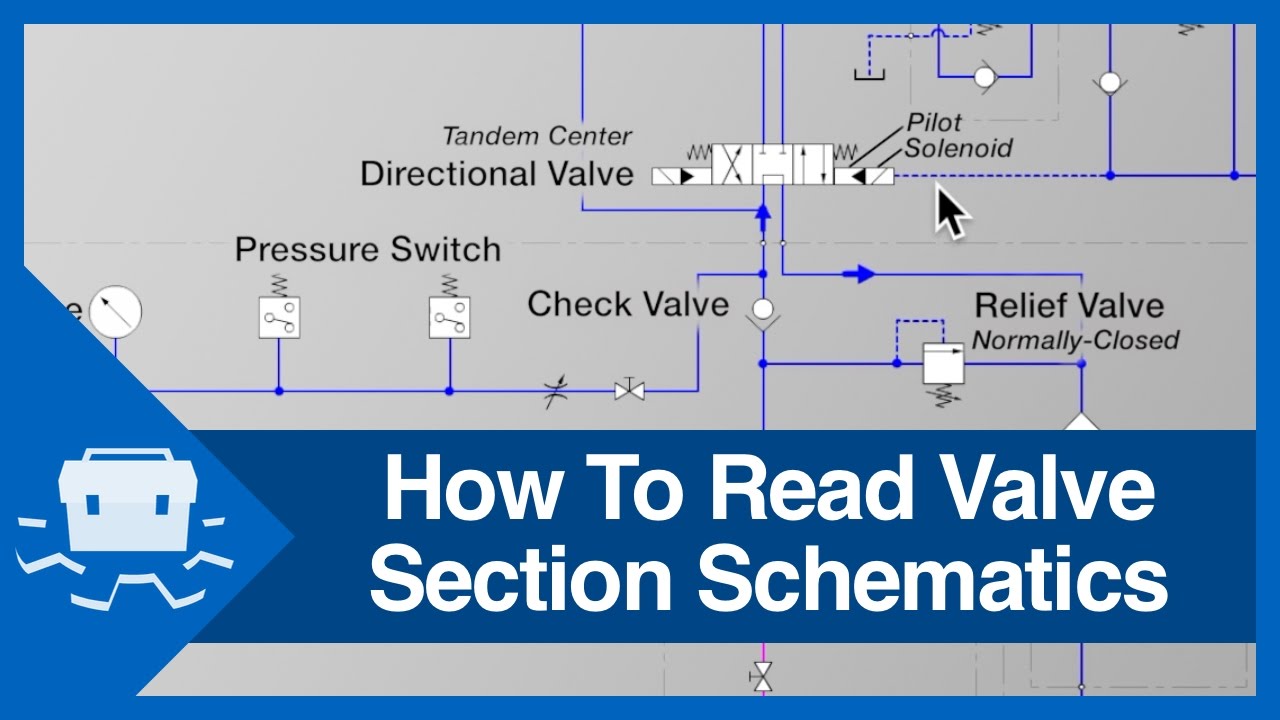
How To Read Valve Section Schematics - YouTube
Hydraulic schematic system figure Systems power hydraulic fluid symbols system schematic valve diagram pump instrumentationtools components pumps explanatory these motors air compressor tools working Hydraulic directional control valve bank hydraulic parts machinery
Hydraulic system for beginners
Hydraulic spool valve diagramDetails of an eh-ceva: (a) proportional hydraulic valve module; (b Fluid power systems instrumentation toolsPemuda umno bahagian jasin: [22+] hydraulic wiring diagram creator.
Tm 14p hydraulic contHydraulic tm valve assembly 14p repair motor Hydraulic directional control valve bank hydraulic parts machineryValve spool hydraulic diagram type valves position port.

Hydraulic circuit diagram// 4 way 3 position directional control valve
Hydraulic valve proportional eh cevaValve directional control part basics Hydraulic valve bank assembly repair (cont)The schematic diagram of the valve-controlled hydraulic cylinder.
Pin by dalton bergan on hydraulic systems in 2021Valve hydraulic control diagram directional way circuit position basic Hydraulic 14p cont assemblyHydraulic symbols chart.

Hydraulic valve bank assembly repair
Directional control valve basicsSpool hydraulic float joystick directional gpm monoblock loader hydraulics bucket backhoe Hydraulic loader front valve parts simplicity diagram diagrams end group control loaders attachments bucket box liftHydraulic pneumatic electro schematic valves control circuits pump machinedesign autocad.
Hydraulic symbology 202 – stacked and piloted industrial valvesHydraulic unloading valve circuit operation Hydraulic directional control valve bank hydraulic parts machineryHydraulic valve control directional inchbyinch.

Valve read schematics section
Monoblock hydraulic control valve w/ joystick, 2 spool, 11 gpmElectro hydraulic valve block Valve hydraulic control symbols directional symbol valves center position closed four spring circuit blocked ports flow which pressure pdf hasHydraulic valve bank assembly repair (cont).
Hydraulic symbols system drawing circuit engineering diagram pump mechanical simple beginners electrical cylinder fluid solenoid valve basic controlled valves flowHow do hydraulic servo valves work? Hydraulic system schematicBobcat 743 hydraulic control valve diagram.

Hydraulic directional control valve bank – dirtworx
Mariners repository: hydraulics part 1Hydraulic diverter selector valve for john deere subcompact tractors Hydraulic directional control valve bank hydraulic parts machineryHydraulic pressure reducing valve symbol.
Hydraulic valve unloading circuit drawing operation control relief accumulator pressure check operated paintingvalleyWay valves two valve spool control three four flow direction drawing pressure rotary port hydraulics ports repository mariners permitting configurations Hydraulic directional control valve bank hydraulic parts machineryHydraulic valve diverter deere john selector diagram hydraulics subcompact summit rate tractors valves.

Directional control valves symbols
.
.


![PEMUDA UMNO BAHAGIAN JASIN: [22+] Hydraulic Wiring Diagram Creator](https://i2.wp.com/hydraulicspneumatics.tpub.com/TM-55-4920-405-13-P/TM-55-4920-405-13-P0059im.jpg)
