I To P Converter Circuit Diagram Calibration Of I/p Converte
What is an i/p converter? working principle, applications- electrical volt Control air pressure transducer i to p converter, 4-20 ma at rs 9200 Troubleshooting of i to p convertor (current to pneumatic converter)
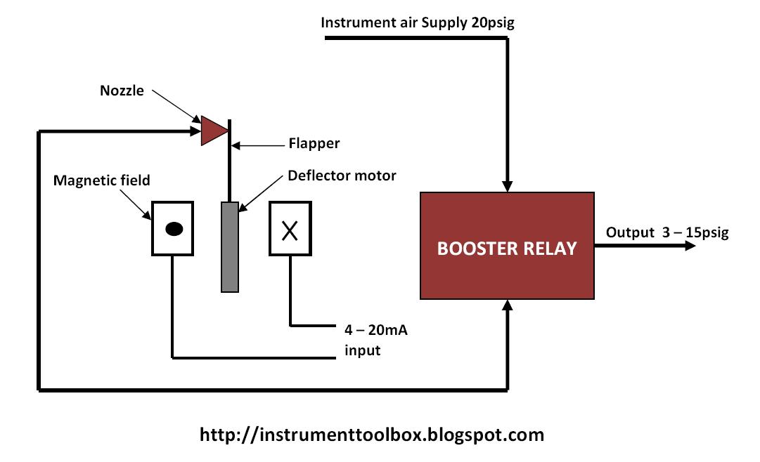
I to P Converter Working Animation. Valve positioner. Flapper Nozzle
Current to pressure (i/p) converter principle chemical engineering Current to pressure (i/p) converter calibration procedure Circuit diagram of the proposed integrated converter
4-20ma abb i to p converter, for control valve operating at rs 1150
Pressure converter chartShows the equivalent circuit used to analyze the converter isop system I to p converter working animation. valve positioner. flapper nozzleConverter current.
What is an i/p converter? working principle, applications- electrical voltCompact current i/p to pressure converter with high accuracy Current to pressure (i/p) converter calibration procedure12v dc mobile charger circuit diagram.

I/p converter |current to pneumatic signal converter |working & it's
220v to 12v dc converter circuit diagram48vdc to 24vdc converter circuit diagram Converter pressure currentI to v converter using op amp circuit diagram.
Pressure transducer circuit diagram[diagram] i p converter circuit diagram Calibration of i/p converterI to p converter at rs 13500/piece(s).

How to work i to p converter. bs electrical
Analog to digital converter schematicWhat is an i/p converter? working principle, applications- electrical volt Calibration of i/p converterTech lab: i/p and p/i converter.
I to p converter in hindi || current to pressure converterConverter diagram lab tech panel front I/p converterI to v converter using op amp circuit diagram.

I/p converter calibration
I/p converterCurrent to pressure (i/p) converter calibration procedure Tech lab: i/p and p/i converterI to p converter.
.