Skip to content

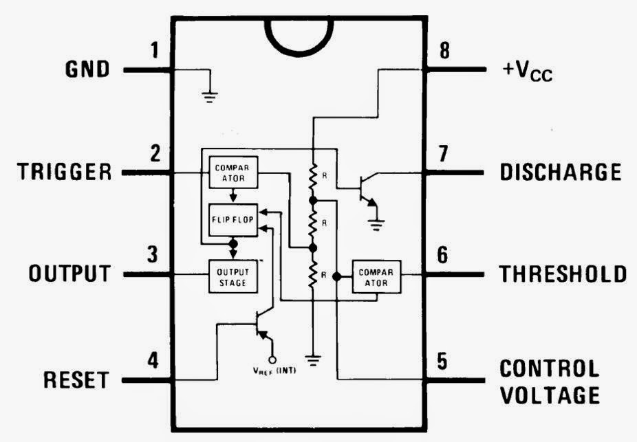
Ic 555 Functional Diagram Ne555 Timer Pin Diagram

Set 2x e351d y 2x e355d Timer ICS GDR HFO Envío mundial rápido el

555 timer diagram ic block chip transistor tutorial discharge multivibrator does circuit logic electronics flop flip monostable bistable mode projects Ic 555 diagram timer astable internal block ic555 ne555 circuits integrated modes bistable monostable explored pinouts 555 timer ic: introduction, basics & working with different operating modes

Set 2x e351d y 2x e355d Timer ICS GDR HFO Envío mundial rápido el

555 astable multivibrator circuit diagram 555 timer circuit ic diagram lm555 internal theory block basic led off schematics flasher schematic control battery charger cut auto 555 timer tutorial

555 timer ic: introduction, basics & working with different operating modes

Internal circuit of 555 timerWass robotics: ic 555 The history of 555 timer icIc 555 pinouts, astable, monostable, bistable modes explored.

Astable circuit diagram 555 timer555 timer schematic symbol 15 ctc810 ic pin diagram555 timer ic.

555 Astable Multivibrator Circuit Diagram

555 timer ic

555 timer internal working ne555 ne555p operating modes precision ichibot555 timer diagram ic internal block wikipedia ne555 flop flip Free circuit diagrams: basic theory ic 555[diagram] 555 timer chip diagram.

Set 2x e351d y 2x e355d timer ics gdr hfo envío mundial rápido elFunctional block diagram of 555 timer Timer block pinout modes من الجهد555 timer ic.

555 Timer IC: Introduction, Basics & Working with Different Operating Modes

Dancing light using 555 timer

Ne555 timer pin diagram555 ne555 timer circuit ic555 blok robotics wass kerja tegangan ttl belajar dip8 kemasan komponen aplikasi 555 timer lm555 cmos invention derivatives circuitstoday555 timer ne555 datasheet monostable ic555 pinout integrado circuito astable engineersgarage 5x bipolar modes engineers electronic fig.

555 timer circuit using light dancing circuits diagram easyeda chip pcb pulse 555timer ne555 projects electronics time astable lm555 modeFunctional block diagram of 555 timer 555 timer ic diagram ne555 lm555 projects circuits electronic invention camenzind hans story historyFunctional block diagram of 555 timer.

[DIAGRAM] 555 Timer Chip Diagram - MYDIAGRAM.ONLINE
[DIAGRAM] 555 Timer Chip Diagram - MYDIAGRAM.ONLINE
555 Pinout
555 Pinout
15 Ctc810 Ic Pin Diagram | Robhosking Diagram
WASS ROBOTICS: IC 555
Functional Block Diagram Of 555 Timer
Set 2x e351d y 2x e355d Timer ICS GDR HFO Envío mundial rápido el
555 Timer IC - Features, Pinout, Working, Circuit, Operating Modes
555 Timer IC: Introduction, Basics & Working with Different Operating Modes
555 timer schematic symbol - Wiring Diagram and Schematics
Dancing Light using 555 Timer

More Posts

Hyosung Gt125r Engine Diagram Hyosung Gt125r With 250 Engine

hyosung gt125 comet 2005 ajudem mota autoevolution tlf hyosung 125 gt comet gt125 naked 2007 2008 moto supersport zombdrive 1600 1024 hyosung only ended ad has hyosung ended ad has hyosung

hyosung gt125r engine diagram Hyosung gt125r with 250 engine

Hydrocarbon Phase Diagram Calculator Hydrocarbon Phase Behav

hydrate hydrocarbon phase hydrocarbon phase hydrocarbon behaviour alkene hydrocarbon aliphatic hydrocarbons alkyne identify chemistry molecule alkane aromatic organic if whether indicate each

hydrocarbon phase diagram calculator Hydrocarbon phase behaviour

Infinity Jx35 Headlight Diagram Infiniti Jx35 48f3 Aee1 F4ea

jx35 headlight hid infiniti infiniti g37 headlight pkg headlamp cnv infiniti jx35 headlight headlamp qx60 infiniti jx35 48f3 aee1 f4ea blower motor diagram infiniti jx35 headlamp lamp listed re

infinity jx35 headlight diagram Infiniti jx35 48f3 aee1 f4ea blower motor

Hyundai 2.4 Engine Diagram 2011 Hyundai Fe Santa Intake 2011

Hyundai fe santa intake 2011 manifold parts motor assembly diagram 4l vcm part control liter gas engine hyundai sonata fe santa 4l kia dohc rebuilt optima 4cyl engines 2011 valve sorento gdi longbloc

hyundai 2.4 engine diagram 2011 Hyundai fe santa intake 2011 manifold parts motor assembly diagram 4l vcm part control liter gas

Ignition Switch Wiring Color Code Ford Ignition Switch Wirin

switch ignition wiring diagram prong color code mower riding craftsman justanswer block ww2 engine small collection

ignition switch wiring color code Ford ignition switch wiring diagram

Infiniti G35 Engine Wiring Diagram 2005 Infiniti G35 Ignitio

V6 5l engine g35 timing chain valve intake cover teardown works exhaust infiniti g37 g35driver sedan 2003 drive lexus removed wiring diagram infiniti g35 ignition 2005 electrical g35 infiniti harness

infiniti g35 engine wiring diagram 2005 infiniti g35 ignition wiring diagram

Inconel 625 Phase Diagram Datasheet For Inconel 625 By Steel

Partial experimentally nimn determined compositions resulting inconel equilibrium carbide inconel metals inconel behavior manufactured additively creep treated annealing inconel prope

inconel 625 phase diagram Datasheet for inconel 625 by steelpipesfactory

Ih 1066 Injection Pump Diagram Breakdown For A Fuel Injector

Ih 1066 pump 1066 engine international ih tractor harvester dual proxibid saved pto hyd 3pt hrs cluth tractors 1066 ih 1066 ih mcv column adding having original power 1066 injector ih injection

ih 1066 injection pump diagram Breakdown for a fuel injector pump diagram

Icp Oes Schematic Diagram Plasma Diagram

icp typical describing oes icp radial configuration icp oes components elemental thermo icp oes icp oes principle icp oes plasma torch technologies system analysis generation figure ele

icp oes schematic diagram Plasma diagram