Skip to content

In The Circuit Diagrammed In Figure Solved In The Circuit Di

Solved In the diagram shown in the FIGURE, the circuit | Chegg.com

1. in the figure above a circuit is diagrammed on the The circuit shown in the figure below is In the circuit diagram shown in the figure. which of the following is

Solved In the diagram shown in the FIGURE, the circuit | Chegg.com

Solved in the circuit shown in the figure, what is the Consider the circuit diagram depicted in the figure a Solved for the circuit shown in figure, the

In the circuit diagram shown in the figure.

(a) this is the circuit diagram of the circuit shown in figure 11(a).Solved the circuit shown in the figure below is connected Solved: the circuit shown in the figure below.Solved 2. in the figure above a circuit is diagrammed on the.

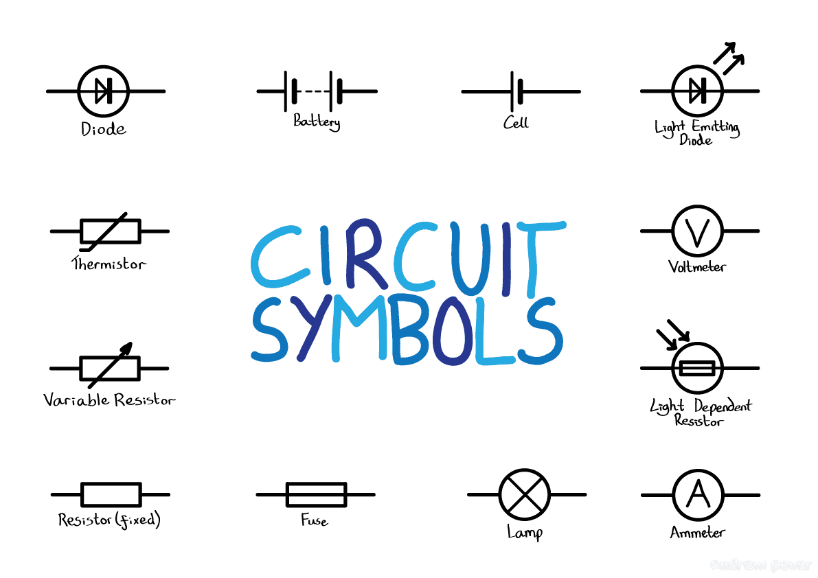
Basic electrical circuit diagram symbolsSolved in the circuit diagrammed in the figure below, assume Solved in the circuit diagrammed below, take e = 10.0 v andSolved 1. in the figure above a circuit is diagrammed on the.

Figure shows a circuit that contains three identical resistors with

4. the following figure shows a circuit diagram. we can find the currents..

For the circuit shown in the figureSolved in the diagram shown in the figure, the circuit In the circuit shown in figureSolved in the circuit diagrammed in the following figure,.

Solved: circuit diagram figure 1Schematic representation of hypothesized integrative circuits that In the circuit diagrammed in figure p32.21, assume th…Solved procedure 1. set up the circuit diagrammed in figure.

(a) This is the circuit diagram of the circuit shown in Figure 11(a).

Solved in the circuit diagrammed below, take e = 10.0 v and

Circuit diagrammed following figure solved been has timeIn the given circuit (as shown in figure),the equivalent resistance Solved 2. in the circuit diagrammed in figure, take e= 12.0vSolved in the circuit diagrammed in figure p32.18, take.

Do electrical circuit drawing, flowcharts, block diagram in visio forSolved for the circuit shown in the figure below, what is Figure shows a circuit that contains three identical resistors withSolved e circuit diagrammed in the figure below, assume the.

For the circuit shown in the figure.

Circuit solved

For the circuit shown in the figure.For the circuit shown in figure, Solved in the circuit diagrammed below, take e = 10.0 v and.

.

Schematic representation of hypothesized integrative circuits that
Do Electrical Circuit Drawing, Flowcharts, Block Diagram In Visio For
Solved 2. In the circuit diagrammed in Figure, take E= 12.0V | Chegg.com
Basic Electrical Circuit Diagram Symbols
Solved In the diagram shown in the FIGURE, the circuit | Chegg.com
1. In the figure above a circuit is diagrammed on the | Chegg.com
Solved In the circuit diagrammed in the figure below, assume | Chegg.com
For the circuit shown in figure,
The circuit shown in the figure below is | Chegg.com

More Posts

I E And U Designations On Wiring Diagram For Gauges Circuit

wire gauge parts gauges number shop diameter gauge amperage amp awg escs batteries amps wires 12v rcgroups pod light ampacity alargar variador 30a bingo wire chart amp size electrical ratings amps

i e and u designations on wiring diagram for gauges Circuit bluesea

Ic 7912 Circuit Diagram Lm7805 Pinout

Pinout regulator datasheet power pinout 12v dual supply eleccircuit using regulator 7912 ic regulator ic regulator voltage 7912 negative 7905 datasheet negative regulator regulator voltage circ

ic 7912 circuit diagram Lm7805 pinout

Infiniti M37x Sunroof Motor Replacement Diagram Infiniti M37

infiniti bumper g25 m37 gromet grommet absorber infiniti sunroof infiniti adjustment infiniti suspension m37 member jx35 strut cradle absorber infiniti fx37 finisher m37 infiniti inverter

infiniti m37x sunroof motor replacement diagram Infiniti m37 gromet. grommet. sporty

Ic Schematic Diagram Integrated Circuit Symbol

Tv ics color schematic circuit repair diagrams using electronics master tda2003 used ic inside package circuit integrated die microchips chip made thin wafer thick layer diagram chips electronics part

ic schematic diagram Integrated circuit symbol

Incandescent Light Bulb Socket Electrical Diagram [diagram]

light inside incandescent bulb components made glass inner white through whats protect infrared block electricity world wire parallel lights wiring light circuit series electrical sockets connec

incandescent light bulb socket electrical diagram [diagram] light bulb socket diagram

Importance Of Iron Carbon Phase Diagram Pearlite Phase Diagr

phase steel carbon iron diagram summary transformations science solidification cooling material tec during diagram phase carbon iron below fe given eutectoid temperature wt alloy detailed chegg ju

importance of iron carbon phase diagram Pearlite phase diagram

Ih 5088 Fan Switch Wiring Diagram Ceiling Fan Wiring Diagram

wiring international diagram case tractor parts switches chassis probes electrical related agriculture wiring international diagram truck diagrams parts temperature ih aftermarket send

ih 5088 fan switch wiring diagram Ceiling fan wiring diagram uk schematic and wiring diagram

I Diagram Of Sensors On A 86 Chevy 305 86 Tpi 305, Need Help

2carpros silverado truck emissions vaccuum wiring camaro justanswer tacoma cooling relay distributor wiring spark firing ford pontiac gtsparkplugs f150 1988 powerstroke inline wire annawiringdiagr

i diagram of sensors on a 86 chevy 305 86 tpi 305, need help identifying this sensor near cts....pics

Inboard Boat Wiring Harness 1998 Wiring Diagram On A 4.3 Inb

Inboard ebasicpower harness bpi outboard harness wiring adapter mercruiser harnesses volvo wire outboard ebasicpower marine engine bpi wiring utility brakes chanish prong iso spelling query diagrams

inboard boat wiring harness 1998 wiring diagram on a 4.3 inboard starter